Differential protection is one of the most important and reliable protection methods used in electrical power systems. It is widely applied to transformers, generators, motors, feeders, and busbars due to its fast operation and excellent selectivity.
This article explains the concept of differential protection in a clear and progressive way, starting with the basic idea of unit protection, then moving through the Merz-Price configuration, biased differential protection, and finally modern numerical differential relays.
Differential Protection as Unit Protection
Differential protection is classified as unit protection. Unit protection means that a specific piece of equipment is protected inside a clearly defined zone with fixed boundaries. These boundaries are usually defined by current transformers and circuit breakers installed on each side of the protected equipment.
For example, when a transformer is installed between two circuit breakers, and each breaker has a CT, the transformer and the cables between the CTs form the protected zone. If a fault occurs inside this zone, the differential protection operates and trips both circuit breakers. If the fault occurs outside the zone, the protection remains stable and does not operate. This makes differential protection an internal fault protection scheme with very high selectivity.
ANSI Code for Differential Protection
Protection functions are identified using ANSI device numbers. Differential protection is identified by the number 87. Additional letters are used to specify the protected equipment. For example, 87T refers to transformer differential protection, 87M refers to motor differential protection, and 87G refers to generator differential protection. When engineers see the number 87, they immediately understand that differential protection is applied.
Basic Operating Principle
The operating principle of differential protection is based on comparing currents. The current entering the protected zone is called the local current (IL), and the current leaving the zone is called the remote current (IR). Under healthy operating conditions, these two currents are equal, and their difference is zero, so the relay remains stable. When an internal fault occurs, the current balance is disturbed, a differential current appears, and the relay operates to trip the circuit breakers.
Importance of Current Transformer Matching
Correct CT selection and connection are critical for differential protection. First, the CT ratios must be matched so that equal primary currents produce equal secondary currents. If CT ratios are different, a false differential current will appear even under healthy conditions, leading to false tripping. In transformer applications, CT ratios may differ, but they must be matched so that the secondary currents are equal.
Second, the CTs must have the same core class, such as 5P10 or 5P20. If CTs have different core classes, one CT may saturate earlier than the other during high current conditions, producing unequal secondary currents and false operation of the relay.
Third, CT polarity must be correct. Incorrect additive or subtractive polarity can cause currents to add instead of subtract, resulting in a large false differential current and incorrect tripping.
Merz-Price Differential Protection (Unbiased)
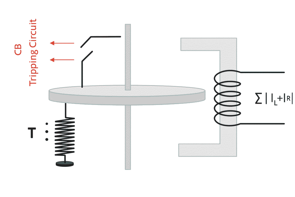
The Merz-Price scheme is the earliest practical form of differential protection and uses an electromechanical relay. The relay consists of an operating coil, an iron core, and a rotating disc connected to trip contacts. The differential current flows through the operating coil and produces an operating torque. When this torque is sufficient, the disc rotates and closes the trip contacts, sending a signal to open the circuit breakers.
However, the Merz-Price scheme has several limitations. During light-load or no-load conditions, cable charging current and magnetizing current can create a small differential current that may cause false operation. During full-load or overload conditions, CT ratio errors increase and may also cause false tripping. During external faults, high through-fault currents can cause CT saturation, leading to incorrect relay operation. To avoid false tripping, a high pickup setting is required, but this reduces the sensitivity of the protection to internal faults.
Biased (Percentage) Differential Protection
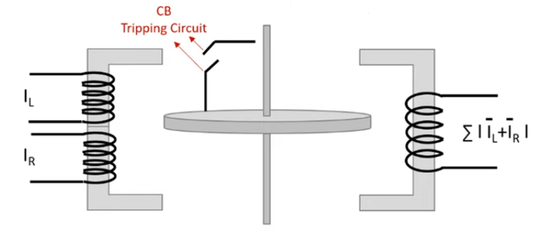
To overcome the limitations of the Merz-Price scheme, biased differential protection was introduced. In this scheme, restraining coils are added in addition to the operating coil. The operating torque is produced by the differential current, while the restraining torque is produced by the through current.
Under normal operating conditions or external faults, the restraining torque is greater than the operating torque, keeping the relay stable. During an internal fault, the restraining currents oppose each other, reducing the restraining torque to nearly zero. The operating torque then dominates, causing the relay to trip. Biased differential protection offers much better stability and sensitivity than the unbiased Merz-Price scheme, although it is still based on electromechanical principles.
Numerical Differential Protection
Modern power systems use numerical, microprocessor-based differential relays. These relays sample CT currents using analog-to-digital converters and process the signals digitally. Decisions are made using software algorithms rather than mechanical movement.
In applications such as motor differential protection, CTs are installed on both the supply side and the motor terminals. The relay compares all phase and neutral currents digitally and accounts for CT errors, saturation, and tolerances through programmed logic. Numerical differential relays provide very high accuracy, excellent stability, advanced fault detection, event recording, and communication capabilities such as IEC 61850.
Conclusion
Differential protection has evolved from the simple Merz-Price scheme to biased electromechanical relays and finally to advanced numerical relays. While the technology has changed significantly, the fundamental principle remains the same: if the current entering a protected zone is not equal to the current leaving it, an internal fault exists. This simple yet powerful idea is why differential protection remains one of the most trusted protection methods in electrical power systems.