In the world of power systems, safety and accuracy are non-negotiable. Measuring high voltages directly is both dangerous and impractical. That’s where voltage transformers—also known as potential transformers (PTs)—step in. These devices are designed not to transfer power but to step down high voltages to safe, standardized levels for accurate monitoring, protection, and control.
This article breaks down what voltage transformers are, how they function, where they’re used, and why they remain a vital component of electrical infrastructure.
What is a Voltage Transformer?
A Voltage Transformer (VT) is a type of instrument transformer used to convert high voltages from the power system into much lower, manageable voltages suitable for meters, relays, and control systems. While typical power transformers transfer energy between circuits, voltage transformers focus on precision and safety, enabling indirect access to high-voltage signals without direct exposure.
Why We Use Voltage Transformers
There are several critical reasons voltage transformers are used in electrical systems:
1. Safe Voltage Measurement
Directly connecting standard voltmeters or relays to high-voltage lines (such as 11 kV or 132 kV) poses serious safety risks. Voltage transformers isolate the high-voltage circuit and safely scale down the voltage to typical values like 100V or 110V, making it suitable for control rooms and metering devices.
2. Accurate Monitoring and Protection
Voltage transformers ensure precise voltage replication through calibrated transformation ratios. This accuracy is vital for triggering protection relays during faults, for ensuring the smooth operation of automation systems, and for accurate billing in utility-scale setups.
3. Compliance with International Standards
Electrical systems must comply with industry standards (like IEC or ANSI), which often require standardized secondary voltages and accuracy classes. Using voltage transformers helps maintain consistency and interoperability across different systems.
How a Voltage Transformer Works
A voltage transformer operates on the principle of electromagnetic induction, the same principle that governs conventional transformers. However, the design is optimized for accuracy rather than power transfer.
Key Components:
- Primary Winding: Connected directly to the high-voltage source.
- Secondary Winding: Outputs a much lower voltage that is proportional to the input.
- Magnetic Core: Laminated steel core that efficiently transfers the magnetic field between windings.
- Insulation System: Ensures electrical isolation between high-voltage and low-voltage sides.
- Ferroresonant Circuit (in some VTs): Used to regulate output voltage under input fluctuations.
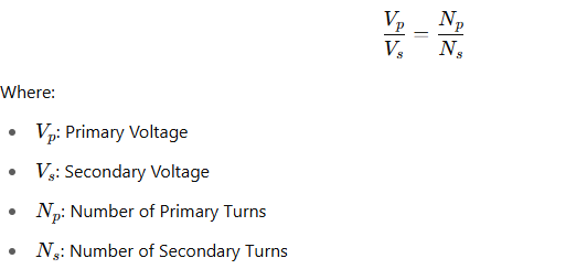
When high AC voltage flows through the primary winding, it creates a magnetic field in the core. This field induces a voltage in the secondary winding. The output voltage remains proportional to the input, following the turns ratio of the transformer.
Turns Ratio Equation:
A typical ratio might be 1000:1, stepping down 11,000V to 11V or 110V.
Types of Voltage Transformers
1. Electromagnetic Voltage Transformers
These are traditional VTs using magnetic cores and windings. Common in distribution systems and control rooms.
2. Capacitive Voltage Transformers (CVTs)
Used in high-voltage transmission systems (above 100kV), CVTs employ capacitors and inductors to divide and transform voltage levels.
Where Voltage Transformers Are Used
- Substations (LV, MV, HV)
- Industrial Automation Panels
- Smart Metering and Energy Monitoring
- SCADA and Control Systems
- Generator Synchronization
- Protection Relay Circuits
Voltage Transformer vs Constant Voltage Transformer
While both devices regulate or transform voltage, they serve different purposes:
- Voltage Transformer (PT): Steps down high voltage for measurement. Prioritizes accuracy and safety.
- Constant Voltage Transformer (CVT): Maintains a constant output voltage despite input fluctuations. Used to ensure consistent power in sensitive equipment.
A CVT is particularly useful in environments with unstable voltage supply, such as in labs, data centers, or equipment with tight voltage tolerances.
Key Factors When Choosing a Voltage Transformer
- Accuracy Class: 0.1, 0.2, 0.5, etc. Lower is better for precise measurements.
- Burden: Maximum load on the secondary side, measured in VA.
- Insulation Level: Should match system voltage to prevent breakdown.
- Installation Conditions: Whether indoor or outdoor, temperature, humidity, and pollution levels all affect transformer selection.
- Frequency: Most are designed for 50Hz or 60Hz systems.
Caution: Do Not Short the Secondary
Shorting the secondary terminals of a VT during operation is dangerous. While under normal conditions the secondary current is minimal, a short circuit causes a large current to flow. This can overheat and destroy the winding, potentially causing shock hazards or equipment damage. For this reason, fuses or circuit breakers are always installed on the secondary side.
Final Thoughts
Voltage transformers are often overlooked, but they are essential to the safe and reliable operation of modern power systems. Whether you’re stepping down 132kV for a substation relay panel or monitoring 11kV on a factory floor, a well-chosen voltage transformer ensures accuracy, safety, and compliance with global standards.
Understanding how they work, where to apply them, and how to install them properly can prevent costly mistakes and improve system performance. Whether you’re an engineer, technician, or student—mastering VTs is a fundamental part of power system knowledge.
I think the admin of this sitee is genuinely working
hard in favcor of his site, since here every matgerial iss quality basedd material. http://Boyarka-Inform.com/
Happy to be one of our family here,, thank you